Map the shift
When does demand occur?
Note base demand, recurring production loads, short peaks, breaks, cleanup periods, and changes between shifts. A single pressure snapshot does not show this pattern.

INDUSTRIAL COMPRESSED AIR
A useful rotary screw compressor comparison goes beyond horsepower. Match the equipment and controls to required CFM, pressure, duty cycle, demand variability, site conditions, and air quality.
Bluegrass Air Power sells Omorfo industrial rotary screw compressors and helps Ohio Valley operations work through selection and quote requirements.
Omorfo equipment
Rotary screw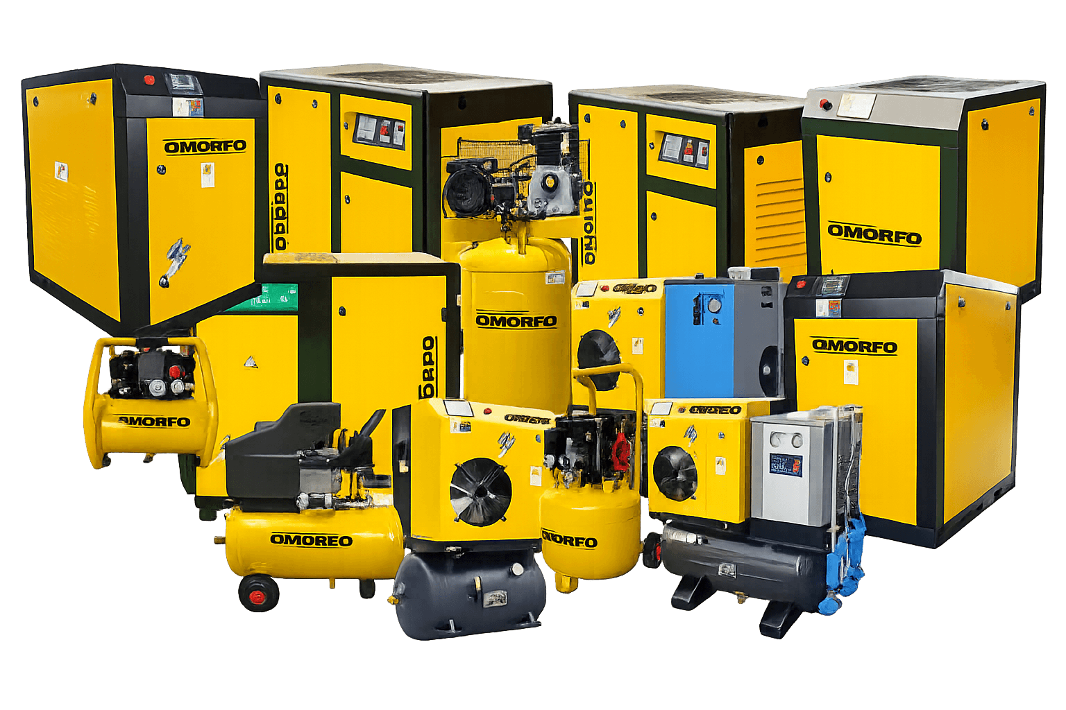
Selection sequence
Demand → controls → site → air treatment → quote
Sustained demand
Rotary screw equipment is commonly evaluated when compressed air is needed for long periods or across production shifts.
Stable system pressure
The compressor, controls, receiver, and distribution system must work together to support the pressure required at the point of use.
System-level efficiency
Energy performance depends on the demand profile, control method, pressure target, treatment equipment, and condition of the air system.
Planned maintenance
Service access, filters, lubricant, separators, drains, and operating conditions should be reviewed before equipment placement.
DUTY CYCLE FIRST
Start with the operating pattern. Rotary screw equipment is commonly evaluated for sustained production demand. A reciprocating, or piston, compressor may deserve comparison when demand is intermittent and the selected model has adequate time to cool. Treat that as a screening step: the manufacturer’s duty-cycle limit for the specific model still controls.
Compare both technologies at the required CFM and PSI, then review daily run hours, demand timing, air quality, receiver capacity, site conditions, and lifecycle cost. A rotary screw label alone does not make a model correct for the load: oversizing can create inefficient part-load behavior and excessive cycling, while undersizing can leave pressure unstable during demand peaks.
Map the shift
Note base demand, recurring production loads, short peaks, breaks, cleanup periods, and changes between shifts. A single pressure snapshot does not show this pattern.
Check the system
Low point-of-use pressure can come from insufficient compressor capacity, but it can also result from restrictive piping, filters, regulators, dryers, or local demand events.
Measure when possible
Flow, pressure, and compressor-power logging across representative operating periods can expose the range that a control strategy must handle. Final sizing should be reviewed using measured demand and qualified installation input.
CFM + PSI
CFM describes airflow; PSI describes pressure. Compare compressor capacity at the required discharge pressure, because rated airflow can change with pressure. Also confirm whether ratings use the same flow convention and reference conditions before comparing models.
CFM
Estimate simultaneous process demand, then account for measured or justified leakage, treatment demand, and planned loads.
PSI
Begin with the highest legitimate point-of-use requirement, then evaluate pressure loss between the compressor and that process.
PROFILE
Average flow alone can hide short peaks. Controls and storage must respond to the real range and timing of demand.
CONTROL STRATEGY
Fixed speed is typically the starting point when compressed-air demand stays steady and predictable. Variable speed is typically evaluated when demand rises and falls across a shift, because motor speed can follow that changing load within the model’s designed operating range. Confirm either choice against representative flow, pressure, and power data plus lifecycle cost; neither label is automatically the right fit.
Review the listed OM100V variable-speed modelScroll horizontally to compare all columns.
| Decision point | Fixed speed | Variable speed |
|---|---|---|
| Demand pattern | Often considered where demand is relatively steady or the compressor can operate effectively within a coordinated system. | Often considered where demand varies within an appropriate operating range for speed control. |
| Capacity control | Motor speed remains fixed while the compressor’s control system manages loaded and part-load operation. | Motor speed changes to follow demand within the equipment’s designed range. |
| What to verify | Part-load behavior, receiver and control setup, unload time, and interaction with any other compressors. | Minimum and maximum operating range, environmental and electrical requirements, and behavior outside the preferred range. |
| Best evidence | Overlay a representative time-at-demand profile with manufacturer performance data at the intended pressure. Compare full- and part-load input power, specific power, minimum turndown, fixed-speed unloaded behavior, and lifecycle cost; use standardized CAGI data sheets when the manufacturer participates. | |
POWER + SITE PREP
A compressor can be correctly sized for airflow and still be poorly suited to the available electrical service, ventilation, access, or piping. Qualified trades and manufacturer requirements should guide final site preparation.
Verify voltage, phase, available capacity, disconnect requirements, and the manufacturer’s installation instructions with qualified electrical support.
Size ventilation or exhaust ducting from the selected package’s manufacturer heat-rejection and cooling-air data, not room size or motor horsepower alone. Include dryers and other heat sources, prevent hot exhaust from returning to equipment intakes, and verify duct pressure loss plus the allowed ambient-temperature range.
Allow room for service panels, filters, fluid changes, component removal, and safe movement around the equipment.
Pipe diameter, layout, receiver volume, drains, and pressure drop affect how the compressor’s rated output reaches the process.
Dust, moisture, temperature, and airborne contaminants can influence equipment location and filtration decisions.
Plan drainage and appropriate condensate management for the compressor, receiver, filters, and dryer rather than treating it as an afterthought.
AIR TREATMENT
Start with the job each component must do. A wet receiver before the dryer can support compressor control and allow moisture to collect before treatment. A dry receiver after treatment can buffer a short demand event without sending that peak flow through the dryer. Final receiver volume and placement depend on the demand event, acceptable pressure change, compressor controls, drainage, and system layout—not motor horsepower alone.
Select the dryer from the required pressure dew point and confirm its corrected capacity covers the highest treated airflow under the least-favorable expected combination of operating pressure, dryer inlet temperature, and ambient temperature. When conditions vary, apply the manufacturer’s correction factors for that limiting case rather than matching an uncorrected dryer rating to compressor horsepower. Refrigerated and desiccant dryers serve different dryness requirements, so use the process and the coldest exposed piping condition to set the target. Then verify pressure loss, filtration, and condensate handling for the complete system.
A properly considered receiver can help separate supply from short demand events and support system control. Volume must be selected for the application.
Dryer type and dew point should reflect ambient conditions, piping exposure, process sensitivity, and the required air quality.
Particulate, coalescing, or other filtration is chosen around the process. Each element also introduces pressure drop that must be considered.
Reliable drains help remove collected condensate. Drain demand and pressure loss belong in the overall system estimate.
LIFECYCLE QUESTIONS
Purchase price matters, but so do energy behavior, maintenance requirements, air treatment, room conditions, downtime planning, and access to manufacturer documentation. Settle these questions while comparing options.
Henderson, Kentucky
Learn how Bluegrass Air Power approaches local industrial compressor selection and quote preparation.
View Henderson compressor guidance →Current equipment
Review current motor, airflow, pressure, controls, and configuration details before requesting application-specific pricing.
View the product catalog →COMPARE OMORFO OPTIONS
Share CFM, PSI, runtime, demand variability, power, site, and air-quality details for a focused rotary screw compressor conversation.